Overview
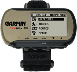
The Garmin ForeTrex 101 is a basic GPS released circa 2005 that runs off of two AAA batteries and has
a serial port for input and output including standard
NMEA.
I've since replaced mine with a more capable GPS but kept it thinking I might think of something
interesting to use it for. I recently found out about the
HC-05 Bluetooth to TTL serial
interface boards. These boards are tiny (2.8 cm x 1.4 cm x 2 mm), low power (10 mA paired), can run
at 3V, and are inexpensive (~ 5 USD). I decided to try adding one to my old ForeTrex 101 so that I
could use it to provide location data to my Android tablet that doesn't have a built-in GPS. The
modification is very simple and works quite well. It's also a great way to get new life out of
otherwise obsolete and unused hardware.
Note that the information provided here is for educational purposes only. Performing these
modifications will void your warranty (are these things even still under warranty?) and may lead to
the GPS and/or HC-05 being irreparably damaged. Proceed at your own risk.
Later in this document I recommend several specific products.
I have no affiliation with their creators or sellers other than being a satisfied user.
The ForeTrex 101 hardware
The ForeTrex 101 is held together using a rubbery glue. To open the case one can simply use a small
screwdriver to pry the two halves apart. It's easiest to start adjacent to the buttons and go from
there. Though I didn't try it, it may be easier to first place the GPS in an oven for about 10
minutes at around 150F (65C) to soften the adhesive. The modification shown here might also work with
the similar ForeTrex 201. If you try this with the 201 be very careful not to damage the battery (i.e.
by heating, puncturing, or short-circuiting it) as I believe battery damage could lead to a nasty fire.
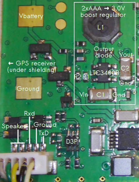
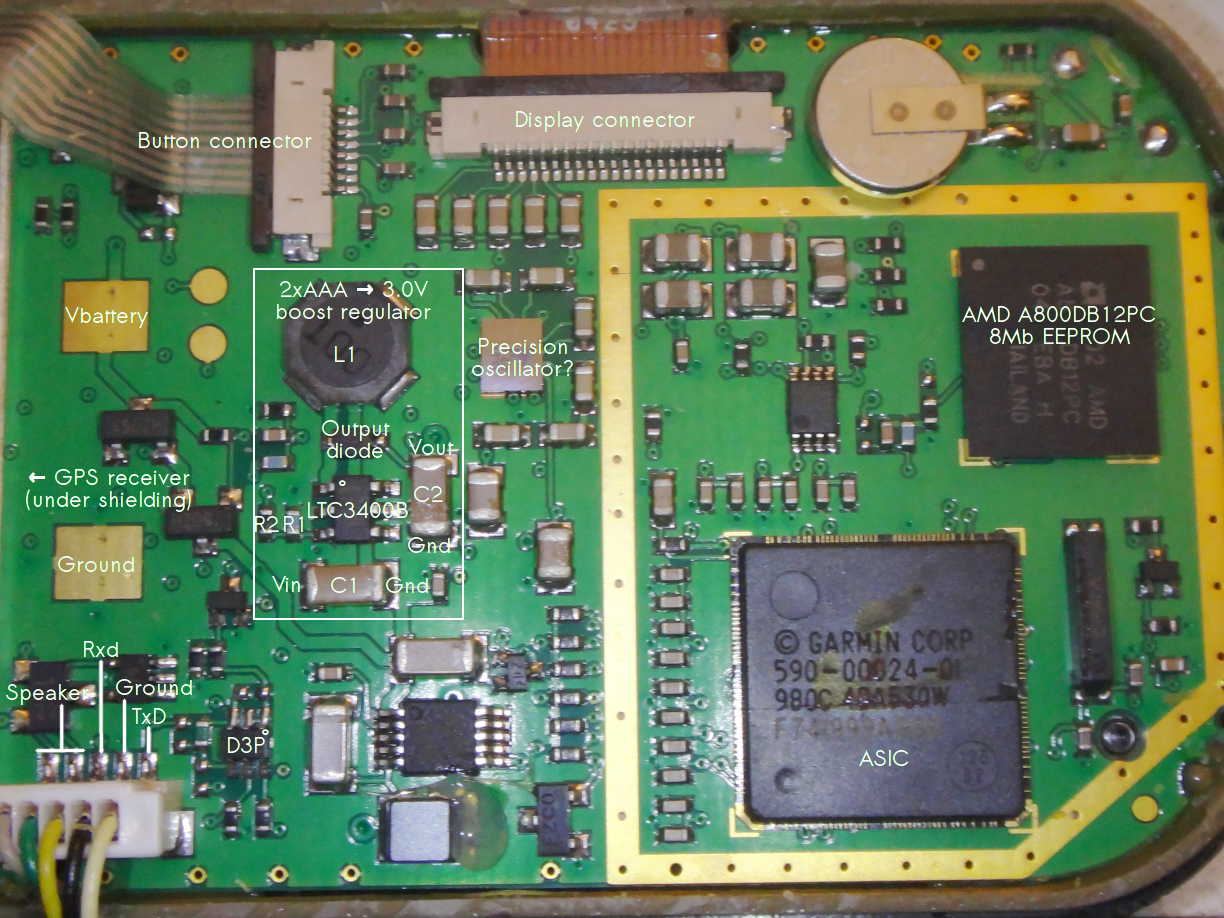
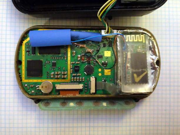
Once you've gotten the case open you'll see the circuit board with the GPS receiver (under the metal
shielding, interface circuitry (in the middle), and computer (shielded with a trace on the circuit
board). The serial port (2.5 mm jack) and speaker are connected to the main board via a 5-pin
header. There's just enough room on top of the GPS receiver shielding to fit the
HC-05
module. Ideally we wouldn't place the Bluetooth transmitter right on top of the sensitive receiver
circuitry but in this case there's no-where else it will fit. To interface the
HC-05
with the GPS we need to find a 3V power source and we need to get the transmitted serial data in TTL
form.
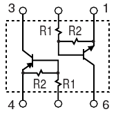
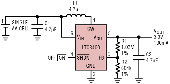
Near the center of the board is a boost converter (
LTC3400B, click for
datasheet) that raises the voltage of the two AAA batteries to 3V. The output appears to drop
to 0V when the GPS is turned off; this is perfect for us since it means the
HC-05 won't
draw power while the unit isn't in use. The circuit used is very similar to the one shown on the
first page of the datasheet (reproduced below) with the addition of the optional output Schottky
diode between pins 1 and 5 (the purpose of the diode is improve efficiency). The values of R1 and
R2 appear to be close to 100k Ω and 70k Ω which gives a V
OUT of 3V.
The easiest place to tap in to this is on either side of capacitor C2 (see photo).
Interestingly, the computer appears to run at 1.8V, not 3V so take care if you decide to interface
directly to it.
To enable NMEA output on the GPS, go to Main menu → Setup → Set interface → I/O format and select NMEA.
The GPS's serial output appears to correctly follow the
RS232 standard
with logic 1 being -3V to -25V and logic 0 being +3V to +25V. The voltage swing appears to be at
least -4V to +1V but I don't have the tools to do a proper measurement. Since the
HC-05 expects
TTL signalling with logic 1 being V
CC (i.e. +3V) and logic 0 being 0V we'll need to either
find the TTL signal on the board or do the conversion ourselves.
The IC adjacent to the serial header seems like an obvious candidate for an RS232 driver. The chip
(labelled D3P
1) is an NPN/PNP transistor pair plus resistors (see schematic to right
and
the datasheet). I was unable to determine how it connects to the serial
port (if indeed it connects to it at all) so I decided instead to convert the RS232 signal back to TTL.
The conversion circuit is shown later in this document. The enterprising reader might try examining the D3P
chip with an oscilloscope and logic analyser to determine whether TTL serial signals are present on this chip.
I suspect that pin 6 is TTL RxD and pin 5 is TTL TxD.
The HC-05 Bluetooth serial module
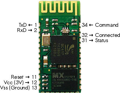
The serial to Bluetooth adapter used is the
HC-05.
These modules are readily available from many sources (just search for them) for about 5 USD.
Make sure that you get the
HC-05 and not the similar, but far less capable,
HC-06.
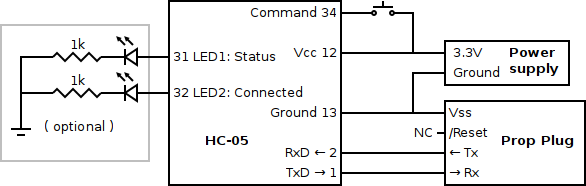
To program the module, you'll need an RS232 or USB to 3.3V TTL serial adapter.
I used a
Prop Plug for this but any adapter capable of 3.3V
TTL serial at 38400 bps will suffice. You will also need a 3.3V power supply. Hook up the circuit shown at
the bottom of this section. The LEDs are optional but can be useful for debugging.
Once you've built the circuit, hook the adapter (Prop Plug in this example) up to the computer and connect
to it using a terminal emulator. On *nix I recommend using
picocom; if you're using Windows
take a look under
Start → Accessories → Communications → Terminal emulator (IIRC;
also, I'm not sure if recent versions of Windows ship with a terminal emulator). You
must set your
terminal emulator to send
CRLF as the line-ending characters.
Change
/dev/ttyUSB0 to the actual location of your serial adapter. The
HC-05 supports
a large number of commands beyond those mentioned below; see
one of the many datasheets for details (the
HC-05 is refered to as the EGBT-045MS in the
linked-to datasheet).
HC-05 programming circuit
-
In all of the commands we'll be using the same serial port settings with the only variable being the speed.
We want to use 8 data bits, no parity, one stop bit (8N1), CRLF
line endings, echo on, no flow control, no init, no reset; for picocom this is given as:
picocom -b BITS_PER_SECOND -d 8 -p n --omap crcrlf -c -f n -i -r SERIAL_PORT_PATH
-
Before applying power to the circuit connect to it at 38400 bps:
picocom -b 38400 -d 8 -p n --omap crcrlf -c -f n -i -r /dev/ttyUSB0
-
Hold down the Command button (or just tie pin 34 to VCC) and then power up the board.
Once the board is powered up you can release the button.
-
Next send a NOOP command to the HC-05 via the serial terminal:
at
You should see the following response in your terminal:
OK
-
Set the HC-05 serial port to 4800 bps 8N1:
at+uart=4800,0,0
-
Set the Bluetooth password (a 4-number string is the most compatible):
at+pswd=nnnn
-
Change the device's name:
at+name="Up to 31 characters"
-
Optionally, set up link encryption. I chose not to do this however you should be aware that
the ForeTrex 101 will include in the NMEA data stream any routes and waypoints you have set.
Only the positions appear to be included, and not the names. Still, if this is a concern for
you then either enable link encryption (determining the proper settings is left as an exercise
for the reader) or delete all routes and waypoints that are on the GPS. In addition, some Android
software will only establish a connection if the link is encrypted.
If you want to enable encryption, one of the following two commands might work:
at+senm=2,1
at+senm=3,1
The default (no encryption) is:
at+senm=0,0
-
If there are any additional settings that you want to change you should do so now.
Once the HC-05 is installed in the GPS you will no longer be able to
access command mode.
-
Make sure that the Command button is released or that pin 34 is floating or grounded.
-
Reset the HC-05:
at+reset
This can also be accomplished by momentarily tieing pin 11 to VCC.
-
Disconnect from the serial port:
Controla Controlq
-
Reconnect at 4800 bps:
picocom -b 4800 -d 8 -p n --omap crcrlf -c -f n -i -r /dev/ttyUSB0
-
Attempt to pair with the HC-05 from your Android device. (You could also use e.g. a
laptop for this and the following steps but that is left as an exercise for the reader.)
-
If the pairing succeeded then install a Bluetooth terminal emulator onto your Android device that
supports non-encrypted connections. I used Bluetooth Terminal by Qwerty
(freeware).
-
Start the Android Bluetooth terminal and make an insecure connection to the HC-05.
-
Test the connection. Any lines that you type in the terminal emulator should appear on the Android device,
Likewise, any lines that you send from the Android terminal should appear in the terminal emulator.
-
If everything is working properly you can proceed to the hardware side of things.
If you've run into problems, start at the top of this list and run through the steps again.
Note that to reliably enter command mode at 38400 bps you'll need to reset the HC-05
with the Command pin held high.
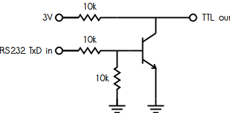
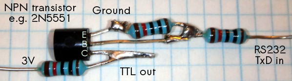
RS232 to TTL adapter
The RS232 to TTL circuit is shown at right. It comprises three 10k Ω resistors and one
general-purpose NPN transistor (I chose a 2N5551 that I had on hand). This circuit only supports data
output; supporting input over Bluetooth would greatly complicate the circuit. Since I have no need for
input (nor a desire to draw more power than is needed) I decided to make the circuit output-only. Two
similar circuits (which do support input) can be found
here
and
here.
The physical circuit is shown below. (Note that different transistors have different pin assignments;
if in doubt, check your transistor's datasheet) The circuit needs to fit into the gap between the battery
compartment and the outer wall of GPS. This space is less than about 1 cm wide (0.4") so the
circuit needs to be long and thin. Solder the components together and, before trimming them, check
that the circuit fits properly. For RS232 TxD in, the resistor's lead is soldered directly to
the 5-pin connector's TxD pin. This lead therefore has to be carefully cut to length and bent
into shape (see photos below). If everything looks good then trim the remaining leads short.
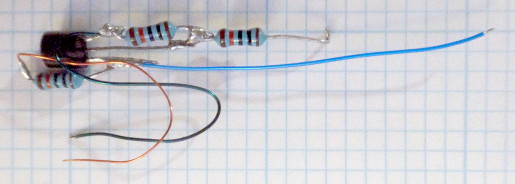
Next cut wires for TTL out
(the blue wire), 3V (the red one), and Ground (the green one). An additional pair of
wires is needed for the HC-05's VCC and Ground lines. I recommend
using wire-wrapping wire for the connections. This wire is semi-rigid and the insulation resists heat very
well while still being easy to scrape off using an X-Acto knife. Solder three of the wires onto
the converter circuit as shown in the photo below. One red wire goes to 3V, one green wire goes to
Ground, and the blue one goes to TTL out.
The completed adapter, ready to solder onto the board.
Cut some heatshrink tubing to use as insulation (sizes are approximate):
-
For covering the base and emitter pins as well as the RS232 TxD in lead,
use an 11.5 mm long piece of 4 mm diameter tubing (this piece should be put on before
soldering the RS232 TxD in connection.
-
For covering the transistor and collector leads, use a 25 mm length of 7.5 mm diameter tubing.
-
For the HC-05, use a 33 mm piece of 11 mm diameter tubing (slightly shorter than shown in the photo).
Note that despite its intended purpose, the tubing is not shrunk onto the components; this should make
any future rework easier. If you don't have appropriate tubing, electrical tape would make an OK (but less than ideal) substitute.
The wires can now be soldered into place (see photo at right for locations).
- The RS232 TxD in lead should be connected to the TxD pin on the GPS board's 5-pin connector.
- Connect one end of each of the two VCC wires (red) to VOUT on C2.
- The remaining loose VCC wire should connect to pin 12 (VCC) of the HC-05.
- Connect one end of each of the two Ground (VSS) wires (green) to Gnd on C2.
- The remaining loose Ground (VSS) wire should connect to pin 13 (VSS) of the HC-05.
- The loose end of the TTL out wire (blue) should connect to pin 2 (RxD) of the HC-05.
- The remaining heatshrink tubing can now be placed over the converter circuit and over the HC-05.
The completed circuit is shown below.
The case can now be re-assembled.
Make sure that none of the wires are blocking the power contacts. In the photo above one of the red VCC
lines needs to be moved out of the way. Also verify that no metal on the added circuitry is touching the existing
circuitry. With the screen facing down, carefully push the two halves back together.
Put in a couple of AAA batteries in, press the power button and see whether it powers up. If it doesn't then re-open
the case and check whether anything is preventing the case from seating. In particular, make sure that the HC-05
isn't getting in the way and that there are no wires over the two square power contacts on the circuit board. You
might also try (gently!) bending the two contacts on the battery compartment towards the inside of the GPS. If you're
still not able to get it to power on you should double-check that all your wiring is correct.
To reseal the case some kind of
contact adhesive (think heavy-duty rubber cement) would probably work best.
Carefully remove any existing adhesive from the case. Next, apply a thin layer to the mating groove on each side of the case, let it dry, and then firmly press the two sides together.
A few notes on soldering
Be very careful when you're doing the surface mount soldering. If you get a blob of solder in the wrong
place it will be very difficult to remove. Likewise, if you de-solder a surface mount component you'll
have a rather fun time getting it soldered back into place. If you've never done surface mount work
before I recommend practicing on e.g. an old PCI card before doing it for real. I recommend using fine
silver solder; the stuff I use is 0.22" (0.5 mm) 62/32/6 though thinner would be better. A fine tip, low
wattage (15W is fine) soldering iron is essential. If you can't find a fine tip for your iron you can
modify a larger tip by filing it to a thin point (the last 3 mm or so should be no more than about 1 mm
in diameter). For the surface-mount connections it's probably easiest to do the soldering by first
tinning each side of the connection then placing the two (or three) sides together and reflowing the
solder to make the final connection.
Android software
Once you've completed the modifications to the ForeTrex 101, you can set up the Android side of things.
-
Pair the ForeTrex 101 with your Android device:
- Go into the Bluetooth settings on your Android device.
- Unpair the device that you had previously paired.
- Power on the ForeTrex 101.
- From the Bluetooth menu, select Search for devices.
- The ForeTrex 101 should show up in the list.
- Pair with the ForeTrex 101 using the password that you entered when you set it up.
- If all went well, the ForeTrex 101 should now be paired to your Android device.
-
Test the connection:
- On the ForeTrex 101 go to Main menu → Setup → Set interface → I/O format and select NMEA.
- Start the Android Bluetooth terminal
- Attempt to make an insecure connection to the ForeTrex 101.
- If your ForeTrex 101 is correctly wired you should now see a stream of NMEA data in the terminal.
-
If the display remains blank then double-check the electrical connections in the ForeTrex 101.
In particular, make sure that the RS232 TxD in lead is connected to TxD on the GPS
board's 5-pin connector, that there is no short between the Ground and TxD pins on
the 5-pin connector, and that TTL out (the blue wire) is connected to pin 2 on the HC-05.
-
Once you've verified that NMEA data is being received, you can drop the connection. The easiest way to
do this is to simply turn Bluetooth off and then on again on the Android device.
-
Configure Android to use the Bluetooth GPS:
- Install Bluetooth GPS by GG MobLab (mild adware)
- On the ForeTrex 101 go to Main menu → Setup → Set system → GPS mode and select Demo.
- Next, launch Bluetooth GPS on your Android device.
-
Open the app's settings and set the following:
- Reconnect → on
- Reconnect interval → 10s
- Use Insecure Connection → on
You may also need to set:
- Connection Workaround → on
- Other Workaround → on
-
Press ← to exit out of the settings menu
-
Make sure that Enable Mock GPS Provider is checked.
-
Choose the ForeTrex 101 from the list of paired devices and tap on Connect.
-
You should now see (demo) GPS data appear on the screen.
- Next, launch Google Maps. You should see your current (fake) position being displayed.
-
Another app to try is MyTrails by FrogSparks.
This is very good software even without a GPS; with a GPS it should be even better. Highly recommended.
Now that the ForeTrex 101 has been set up as a GPS provider under Android you can start using it for real.
On the ForeTrex 101 go to Main menu → Setup → Set system → GPS mode and select Normal,
WAAS, or Battery save. This will provide real data to Android as opposed to demo data. One annoyance is
that Bluetooth GPS will drop the connection if it doesn't see a valid position in the NMEA stream. In practical
terms this means that if the ForeTrex 101 loses a fix on the satellites (which it does a lot) then the connection will
also drop. This is why Bluetooth GPS needs to have a very short reconnect interval set.